Security News
Crates.io Users Targeted by Phishing Emails
The Rust Security Response WG is warning of phishing emails from rustfoundation.dev targeting crates.io users.
You can install morbius from npm:
yarn add morbius
Then import it into your project:
import { Graph } from "morbius";
Graph contains a generalized DAG structure formed from nodes and relationships between nodes. In terms of the graph, each vertex is a node that can contain arbitrary data while each edge is a relationship between two nodes. Relationships are in grammar form: the subject, the predicate and the object.
For example:
Parent --- "has child" ---> Child
The graph itself does not initially contain any nodes or relationships. You can begin creating the graph using graph.createNode():
  import { Graph } from "morbius";

  const graph = new Graph();
  const rootId = graph.createNode("node", { value: 1 });
             rootId
             +---------------+
             |  value: 1     |
             +---------------+
Additional nodes can be created.
const node1 = graph.createNode("node", { value: 2 });
              id: rootId                 id: (auto)
             +---------------+           +---------------+
             |  value: 1     |           |  value: 2     |
             +---------------+           +---------------+
In the above examples you can see that the node was constructed with a type (a simple string, in this case "node") and a data payload, { value: 2 }.
In addition the node was given an id automatically, and this is returned by createNode(). This id is how you can refer to nodes throughout the API. Holding onto the actual node is generally a bad idea because mutations will cause the node to change, so ids are important. You can also pass in your own id with the data. e.g { id: 123, value: 1 }.
Nodes can also have tags, which can also be supplied within the data as an array of strings, for example: {id: 123, tags: ["a", "b"], value: 1}.
Nodes can be deleted from the graph nodes with deleteNode(). This will remove both the node and all relationships to and from it.
Once you have more than one node you can build up the graph by creating new adding relationships.
  import { Graph, Predicate } from "morbius";

  const graph = new Graph();
  const node1 = graph.createNode("node", { value: 1 });
  const node2 = graph.createNode("node", { value: 2 });

  // Add relationship
  graph.addRelationship(node1, Predicate.hasChild, node2);
              node1                      node2
             +---------------+           +---------------+
             |  value: 1     |---------->|  value: 2     |
             +---------------+     |     +---------------+
                              "has child"
Here we use addRelationship() to make a connection between node1 and node2. In this case we represent a parent with one child.
The Predicate object contains several pre-baked predicates, such as hasChild used here, but you can make your own. In creating a forward (downstream) relationship in the DAG, you also create an upstream relationship. In this case there will be a corresponding relationship from node2 to the node1 called "has parent". These forward and reverse relationships are defined in the Predicate and managed as you add and remove relationships. Currently, you always create the relationship in the forward (downstream) direction.
You can also remove relationships one by one:
graph.dlRelationship("node1", Predicate.hasChild, "node3");
Or either upstream or downstream from a node:
graph.deleteRelationships(nodeId);
graph.deleteUpstreamRelationships(nodeId);
To build circuits we build up a topology that can represent many possible configurations of our network. We'll represent this with two principles:
At the highest level we have a Graph. The graph contains the complete tree of circuit detail we wish to model.
For this example, lets create a single "circuit" at the top. For now we'll give it mock data {value: 1}, but this could be any JSON data. We'll also specify the id using our "z" number notation.
  const graph = new Graph();
  const circuitId = graph.createNode("circuit", { id: "z0001", value: 1 });
The first abstraction is that a circuit is just a piece of meta data, not a description of its connections and endpoint. The details of its topology is represented further down the graph and so can be represented in many ways. To do this we have a notion that we can "expand" the circuit into more detailed representations.
Notes on this:
Let's make a new group and connect it to our circuit:
  // make the group
  const groupId = graph.createNode("group", {
    id: "group1"
    tags: ["physical"]
  });

  // connect to our circuit
  graph.addRelationship(circuitId, Predicate.expandsTo, groupId);
We now have a graph that looks like this:
             +---------------+
             |Circuit: z0001 |
             +---------------+
             | value: 1      |
             +-------+-------+
                     |
                     | "expands to"
                     |
             +===============+
             |Group: group1  |
             +---------------+
             | ["physical"]  |
             +---------------+
Our group can now contain members, which for our circuit logic represent the internal topology of the circuit this group expands to.
  // create three nodes to represent 3 endpoints
  const port1 = graph.createNode("port", {id: "ep1", value: 3});
  const port2 = graph.createNode("port", {id: "ep2", value: 4});
  const port3 = graph.createNode("port", {id: "ep3", value: 5});

  // connect the nodes to the group as members of that group
  graph.addRelationship(group, Predicate.hasMember, port1);
  graph.addRelationship(group, Predicate.hasMember, port2);
  graph.addRelationship(group, Predicate.hasMember, port3);
We might draw this construction as follows:
                Circuit z0001
                     o
                     |
   +----------------------------------+
   |        group1 [physical]         |
   |----------------------------------|
 a o                 o                o z
   |port1          node2         port3|
   +----------------------------------+
Now we are attaching some meaning to the notion of members here. We are saying:
A connection itself is another type of node, and is also just a member of the group. Therefore, the group is the container to both the ports and the connections between those ports. Since relationships are always ordered, ports define the order of the connections, while the connection nodes themselves define, in their downstream "connects" relationships, the ports they connect between.
    -----------+ has member                       +------------+
               |--------------------------------->| endpoint1  |
               |          +-----------+           |            |
               |          |connection |---------->|            |
        group  |--------->|           | connects  +------------+
               |          |           |           +------------+
               |          |           |---------->| endpoint2  |
               |          +-----------+           |            |
               |--------------------------------->|            |
               |                                  +------------+
    -----------+
Here we create the above graph:
  // Add the first connection, defining both the connection
  // node and the relationships to the nodes that it connects
  const connect1 = graph.createNode("connection", {
      id: "port1_to_port2", tags: ["leased"]
  });
  graph.addRelationship(connect1, Predicate.connects, port1);
  graph.addRelationship(connect1, Predicate.connects, port2);

  // Similarly define the second connection
  const connect2 = graph.createNode("connection", {
      id: "port2_to_port3", tags: ["leased"]
  });
  graph.addRelationship(connect2, Predicate.connects, port2);
  graph.addRelationship(connect2, Predicate.connects, port3);

  // Lastly, the two connections are themselves members of the group
  graph.addRelationship(group, Predicate.hasMember, connect1);
  graph.addRelationship(group, Predicate.hasMember, connect2);
We have now created the basics of our our graph. We can, of course, use the Graph API to query and change the relationships. For example, here's a list of all the ports in this group:
  graph.getRelatedNodes(group, Predicate.hasMember, "port"));
  // List [ "ep1", "ep2", "ep3" ]
And here's a list of the connections:
  const edges = graph.getRelatedNodes(group, Predicate.hasMember, "connection")
      .forEach(connection => {
          const connections =
              graph.getRelatedNodes(connection, Predicate.connects);
          console.log(" - ", connection, connections);
      });
  // Connections: List [ "port1_to_port2", "port2_to_port3" ]
  //   - port1_to_port2 List [ "ep1", "ep2" ]
  //   - port2_to_port3 List [ "ep2", "ep3" ]
To extend the model down to any level of detail we can associate a "connection" with a "group" in the same way we associated a circuit with a group earlier. In this case the semantics are slightly different though. The group would contain just additional detail while sharing the a and z ends.
To illustrate, in the diagram below, node2 and node3 are members of group1. But we would like to show more detail for the connection between node2 and node3 so we create a connection to group2. Group2 then contains an addition node (node5) and two additional connections.
                  Circuit
                     o
                     |
   +---------------------------------+
   |        group1 [physical]        |
   |---------------------------------|
 a O-----------o=========o-----------O z
   |node1    node2  |  node3    node4|
   +--------------- | ---------------+
                    |
        +-----------------------+
        |        group2         |
        |-----------------------|
      a O-----------o-----------O z
        |         node5         |
        +-----------------------+
And as a dependency graph (nodes 1 and 4 omitted for simplicity):
                             +-------------+
                             |             |
                             | group1      |
                             |             |
                             +------+------+
                                    |
                                    |
                             +------v------+
                             |             |
      +----------------------+ connect1    +----------------------+
      |                      |             |                      |
      |                      +------+------+                      |
      |                             |                             |
      |                             |                             |
      |                      +------v------+                      |
      |                      |             |                      |
      |              +-------+ group2      +-------+              |
      |              |       |             |       |              |
      |              |       +------+------+       |              |
      |              |              |              |              |
      |        +-----v-----+        |        +-----v-----+        |
      |        |           |        |        |           |        |
      |        | connect2  |        |        | connect3  |        |
      |        |           |        |        |           |        |
      |        +---+---+---+        |        +---+---+---+        |
      |            |   |            |            |   |            |
+-----v-----+      |   |     +------v------+     |   |      +-----v-----+
|           |      |   |     |             |     |   |      |           |
| node2     <------+   +-----> node5       <-----+   +------> node3     |
|           |                |             |                |           |
+-----------+                +-------------+                +-----------+
FAQs
Graph abstraction built on Immutable.js
The npm package morbius receives a total of 0 weekly downloads. As such, morbius popularity was classified as not popular.
We found that morbius demonstrated a not healthy version release cadence and project activity because the last version was released a year ago. It has 1 open source maintainer collaborating on the project.
Did you know?

Socket for GitHub automatically highlights issues in each pull request and monitors the health of all your open source dependencies. Discover the contents of your packages and block harmful activity before you install or update your dependencies.

Security News
The Rust Security Response WG is warning of phishing emails from rustfoundation.dev targeting crates.io users.

Product
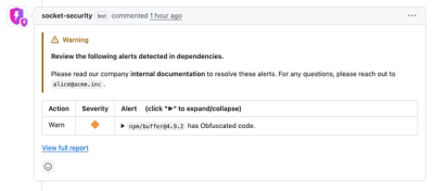
Socket now lets you customize pull request alert headers, helping security teams share clear guidance right in PRs to speed reviews and reduce back-and-forth.

Product
Socket's Rust support is moving to Beta: all users can scan Cargo projects and generate SBOMs, including Cargo.toml-only crates, with Rust-aware supply chain checks.