screen2table
screen2table is a simple Windows GUI program that facilitates adding culvert and cross-section data in a hydraulic model when the original data is not in a file format that can be easily processed (image, PDF, CAD).
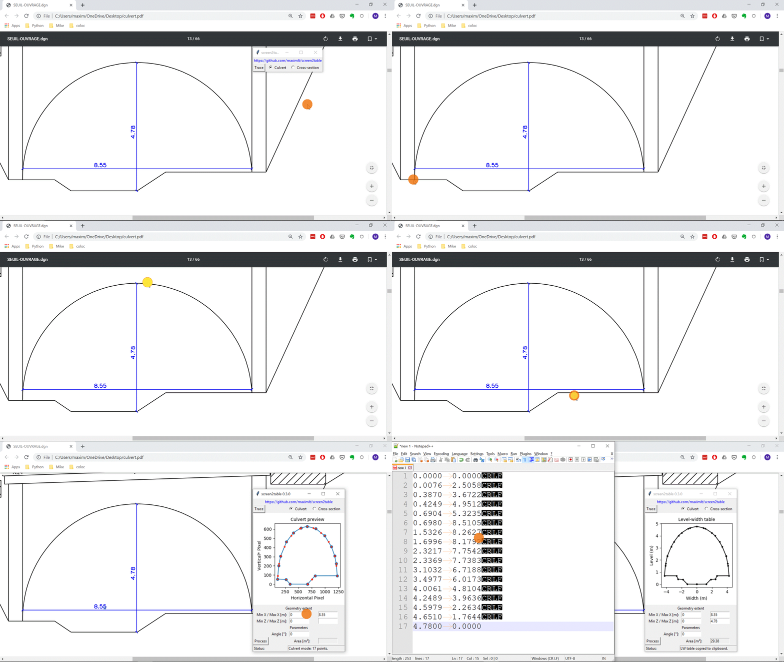
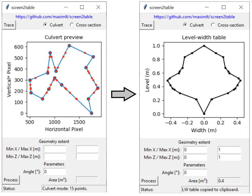
The program allows the user to trace a shape on the screen and to define its dimensions. The traced shape is processed to either generate a Distance-Level table for a cross-section or Level-Width table for a culvert.
As the program was originally developed to facilitate the development of hydraulic models with Mike by DHI, its input options (cross-section or culvert) and its output (table copied to clipboard, tab-separated) are tailored to this specific use case. However, the program may prove to be useful in other situations, such as when one needs to determine the area of a complex polygon saved in a PDF file and whose extent is known.
Rationale
Hydraulic/hydrodynamic models (1D, 2D or 1D/2D) require as input data some geometric description of a river, its in-line structures and the structures lying in the floodplain. A river geometry is usually given as a series of cross-sections (i.e. level of the ground on a line perpendicular to the flow path). The geometry of a structure like a culvert or an arch is often described by a level (or height)-width curve.
Modern softwares provide modellers with methods allowing to import geometric data in a breeze. This is possible only if the input data is given in the right format, which is a GIS format in most cases. Quite frequently though, the data may just be available as drawings saved in a bunch of PDF or CAD files. Modellers have then to resort to more manual, time-consuming, and tedious methods to generate the required data table for developing their model.
screen2table aims to fill this gap by providing a fast and easy way to retrieve that geometric data.
Quick user guide
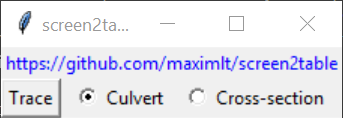
First, the user should select between the culvert or cross-section mode, which have the following outputs:
Culvert (closed chape):
- Area in square meter (displayed with 2 decimals by default)
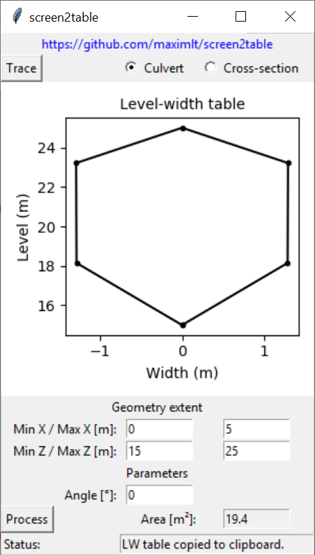
- Level-Width table in meter (copied to clipboard with 4 decimals by default, tab-separated) that starts and end with a width of zero
- Plot of the level-width table (in a rather unusual format, as in Mike Hydro)
Cross-section (open shape):
- Length in meter (displayed with 2 decimals by default)
- X/Z coordinates table in meter (copied to clipboard with 4 decimals by default, tab-separated)
- Plot of the scaled cross-section
The user is then required to perform the two following steps:
- Tracing: The drawing from which the geometry should be copied is traced by left-clicking on its outline. Tracing is stopped with a right-click anywhere on the screen (that does not add a new point). The more zoomed in the drawing on the screen, the closer to the outline the clicks, and the higher the number of points, the more accurate the geometry. Because the program records screen coordinates only, the drawing should not be modified (panned, zoomed in/out) on the screen while tracing it. The traced geometry is displayed in the program for visual inspection after the right-click, new entry boxes are now available for the following step.
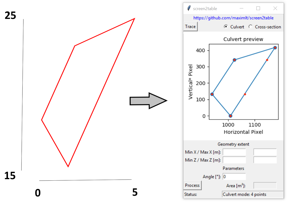
- Scaling and processing: The user provides the geometry extent of the drawing (its bounding box in meter) which is used by the program to scale the recorded geometry to its real dimension and process it further. Optionnaly, an angle in degree can be provided to skew the geometry before processing it. This is for instance useful to horizontally flip a line (angle of 180°).
Technical note
While generating the output for the cross-section mode is straightforward, some more work is done by the program when it processes culvert data:
- Additional interpolated points are added to the geometry at each clicked level (vertical screen coordinates), this is required because the width needs to be calculated at each clicked point. The interpolated points are represented with red circles on the culvert plot.
- If two or more points were clicked on the exact same level (in practice, it means two or more clicks hit the exact same pixel row), the question arises as to which width should be attributed to this level (the smallest? the largest?). The trick used to make the width computation easier is to transform those points so that there are two and only two points at the same level within a polygon. This is done by adding/subtracting small random numbers to those points. While this may look like a numerical trick, this is actually realistic: down to a microscopic scale there are never two indentical level measures (this is continuous data).
- The width is calculated at each of those clicked/derived levels (there is no regular vertical discretization), be the polygon concave or convex (it cannot be self-intersecting though).
- Rows in the level-width table that are almost identical, defined as an absolute change in both width and level less than 0.1 mm, are considered as duplicates. Only the first one is preserved (why? because Mike Hydro was not very happy with too close points in the resulting level-width table).
Install
screen2table targets Windows only (the clipboard is OS specific) and is developed based on Python 3.7.
Executable
An executable file can be downloaded here. Just run the executable to launch the program.
From source
The package is available on pip:
pip install screen2table
It can then be launched from the command line since an entry point screen2table in created during the install.
Build an executable from source
The executable file was created thanks to PyInstaller. Building it again can be achieved by cloning this repo, installing the dependencies found in requirements_pyinstaller.txt and running the following command from the root directory:
pyinstaller --distpath .\dist_pyinstaller -y --clean --onefile --windowed --add-data "screen2table/configs.cfg;screen2table" --version-file pyinstaller/file_version_info.txt screen2table\screen2table.py
The above line will create a dist folder containing a single executable file, screen2table.exe, which includes Python, the program and its dependencies.
Configuration
A configuration file (configs.cfg) allows the user to tweak some internal parameters (record and stop buttons, fontsize, decimal precision of the output, etc.). It is available only when the program is used as a Python package.
Dependencies
screen2table relies on the following Python packages:
- pynput to record the pixel coordinates of the clicks
- Numpy to derive the metrics and the level-width curve
- Matplotlib to plot the results obviously, but also to support processing complex polygons
- pywin32 to copy the output table to clipboard
The GUI is developed thanks to tkinter that is part of the standard library.
History
screen2table was also a learning project, hence some non-pythonic pieces of code and a number of poor design decisions.
License
MIT License
Copyright (c) 2019 Maxime Liquet
Permission is hereby granted, free of charge, to any person obtaining a copy
of this software and associated documentation files (the "Software"), to deal
in the Software without restriction, including without limitation the rights
to use, copy, modify, merge, publish, distribute, sublicense, and/or sell
copies of the Software, and to permit persons to whom the Software is
furnished to do so, subject to the following conditions:
The above copyright notice and this permission notice shall be included in all
copies or substantial portions of the Software.
THE SOFTWARE IS PROVIDED "AS IS", WITHOUT WARRANTY OF ANY KIND, EXPRESS OR
IMPLIED, INCLUDING BUT NOT LIMITED TO THE WARRANTIES OF MERCHANTABILITY,
FITNESS FOR A PARTICULAR PURPOSE AND NONINFRINGEMENT. IN NO EVENT SHALL THE
AUTHORS OR COPYRIGHT HOLDERS BE LIABLE FOR ANY CLAIM, DAMAGES OR OTHER
LIABILITY, WHETHER IN AN ACTION OF CONTRACT, TORT OR OTHERWISE, ARISING FROM,
OUT OF OR IN CONNECTION WITH THE SOFTWARE OR THE USE OR OTHER DEALINGS IN THE
SOFTWARE.


